Corkscrew or streching an ellipse

Use this forum to ask questions about how to do things in QCAD.

Moderator: andrew

Forum rules

Always indicate your operating system and QCAD version.

Attach drawing files and screenshots.

Post one question per topic.

sancyk
Junior Member
Posts: 17
Joined: Wed Mar 09, 2022 7:32 pm

Corkscrew or streching an ellipse

Post by sancyk » Tue Feb 06, 2024 5:08 pm

Is there a built-in way of stretching an ellipse with one cut point into a "corkscrew" ? The stretch function doesn't seem to be able to do that.

The arrow is perpendicular to the ellipse's plane
Screenshot 2024-02-06 104642.png
Screenshot 2024-02-06 104642.png (4.28 KiB) Viewed 1834 times

User avatar
andrew
Site Admin
Posts: 9063
Joined: Fri Mar 30, 2007 6:07 am

Re: Corkscrew or streching an ellipse

Post by andrew » Tue Feb 06, 2024 5:19 pm

I don't see how this would be mathematically defined.

Perhaps a spline is better suited for what you are trying to do?

sancyk
Junior Member
Posts: 17
Joined: Wed Mar 09, 2022 7:32 pm

Re: Corkscrew or streching an ellipse

Post by sancyk » Tue Feb 06, 2024 5:50 pm

a spline is what I ended up doing but I was wondering if there was an easier way.

Essentially, it's an helix in an isometric view. I'm sure there's a mathematical representation of that, but it's been too long since I've done that kind of math.
Screenshot 2024-02-06 115107.png
Screenshot 2024-02-06 115107.png (5.69 KiB) Viewed 1821 times

User avatar
Chips&Chips
Full Member
Posts: 68
Joined: Mon Nov 13, 2023 12:15 pm

Re: Corkscrew or streching an ellipse

Post by Chips&Chips » Mon Feb 12, 2024 2:30 pm

I have faced that problem when drawing schematic symbols of coils and transformers. The 3D view of a helix is exactly what is generally used for the coil in these drawings. It is easy for a rough helix to be drawn by hand, which is probably why they are used - grandfathered in from the old days, so to speak. But I have used about a half dozen 2D CAD programs and none of them, in my memory, could do this accurately.

My work-around is to use two arcs, about 90 degrees each and connecting them at one end, sort of football shaped. The other ends are stopped somewhat short of actually meeting and the next "coil" is attached with those points so each coil (pair of arcs) is offset from the previous. This was good enough to get the idea across.

I guess you could replace the points of joining with more arcs with smaller radii (chamfers) if you need a better approximation. This would be sort of like the old manual drafting method of approximating an ellipse with four arcs. It ain't perfect, but it can look nice. Of course more arcs adds more size to the part so it's a compromise.

Another way, which would probably be a lot of work, would be to create the helix in a 3D CAD program and take a screen shot. Then import that screen shot into QCAD and either just use it or draw over it with splines or whatever.
Paul A.
SE Texas
Windows 10
QCAD V 3.29.3.0

User avatar
Chips&Chips
Full Member
Posts: 68
Joined: Mon Nov 13, 2023 12:15 pm

Re: Corkscrew or streching an ellipse

Post by Chips&Chips » Sun Feb 25, 2024 1:29 pm

My attached photo shows a helix simulated with an ellipse and an arc. The red is an ellipse with a segment removed. That elliptical segment is repeated up and down. And the green is an arc that was sized to fit between two adjacent copies. It is also repeated. It is a fairly good approximation.

EllipseAndArcHelix.jpg
EllipseAndArcHelix.jpg (195.04 KiB) Viewed 1252 times
Paul A.
SE Texas
Windows 10
QCAD V 3.29.3.0

CVH
Premier Member
Posts: 3481
Joined: Wed Sep 27, 2017 4:17 pm

Re: Corkscrew or streching an ellipse

Post by CVH » Sun Feb 25, 2024 3:44 pm

Already looking far better. :P

Although it is not a Helix or Corkscrew in perspective ...
The approximation by an ellipse is fairly logical because a winding is about a circle an in perspective that is an ellipse.
The rather short arc is a nice replacement for yet another part of an ellipse.

Together it will yield a good approximation at low rendering calculation costs.
Nice :!:

Now I wonder on how good the approximation is.
Would you want to consider to share your design within a drawing file?
I expect that the curvature should differ for the far and the near part while that is symmetric in your case.

Regards,
CVH

User avatar
Chips&Chips
Full Member
Posts: 68
Joined: Mon Nov 13, 2023 12:15 pm

Re: Corkscrew or streching an ellipse

Post by Chips&Chips » Mon Feb 26, 2024 4:18 am

I am attaching the file for that helix part.

I had a bit of a problem making it and a compromise was necessary. That was good enough for my purpose which was a nice looking schematic symbol. Accuracy was not really necessary. As you know I am a QCAD newbee so perhaps you know of a way to do that I could not find.

Drawing and removing a part of the ellipse was trivial. I simply drew a vertical line and used the Break Out Segment command in the Modify menu. But I could not find a way to precisely draw an arc between the end of one ellipse and the opposite end of the next, making it tangent to both. Ideally I wanted to specify the middle point of the arc, but that would have been greedy. I tried the Tangent restraint but could not get it to work. So I just zoomed in tight and drew the arc by sight. Then the Trim Both command, also in the Modify menu to have the arc and ellipse meet at a point. It came out great looking, but is not precise even for the use of an arc for the approximation to the helix.

If by "far and the near part" you mean the top and bottom ends of the helix in my drawing, then the partial ellipse and the arc are exactly the same at both ends. I did not make any effort at true perspective. It is only a nice looking symbol.

And YES, I was trying to avoid elements, like a spline, that would require excessive rendering time. This helix will be used in a number of schematic symbols and more than one may be on a given drawing.
Attachments
CoilWithCTVert800.dxf
(102.34 KiB) Downloaded 44 times
Paul A.
SE Texas
Windows 10
QCAD V 3.29.3.0

CVH
Premier Member
Posts: 3481
Joined: Wed Sep 27, 2017 4:17 pm

Re: Corkscrew or streching an ellipse

Post by CVH » Mon Feb 26, 2024 7:00 am

Chips&Chips wrote:
Mon Feb 26, 2024 4:18 am
But I could not find a way to precisely draw an arc between the end of one ellipse and the opposite end of the next, making it tangent to both
Indeed kinda problematic and remark that the lower part of your little arcs 'overlaps' with the 'next' ellipse arc.
+ There is a lack of tangent arc drawing methods but that is usually solvable with full circles and trimming.
+ Tangent to ellipses is only provided for a few line tools.

The solution is drawing a normal or tangent at the intended (end-)point on (of) the ellipse (arc).

1) Let us first agree that in this symmetric setup all endpoints of the ellipse arcs are trimmed to a vertical line.
... Depending the situation that may fail with ellipse arcs using Trim (RM) because it only works in one direction.
... Auto trim (AX) may be a solution when there is nothing else to trim to ...
... Otherwise alter the Start or End angle so that it is too long and Break away (D2) the excess.
2) For clarity I have included point entities of interest in Mode 32, see Drawing Preferences .. General .. Points Display.
3a) Draw 2 auxiliary lines from an endpoint to the foci of the ellipse.
... The foci are reference points and displayed when you select an ellipse (arc).
... Harder to select at the open side but these are symmetric and one can mirror the other over with regards to the ellipse orientation.
3b) Construct the angle bisector of these 2 auxiliary lines.
4) The normal or tangent is orthogonal to the angle bisector in the intended (end-)point.
5a) Construct a circle from a tangent and two points (CT1)
... Indicate the normal (Cyan) and the two endpoints (green).
5b) Remove all auxiliary constructions and trim the circle with Break out Segment (D2) removing (see Option Toolbar) the obsolete part.

Steps are visualized in the attached file each on a separate layer, just make them visible one by one for stepping trough.
I added 'Far' and 'Near' on an extra layer. :wink:
HowTo_ArcTangent2ptOfEllipses.dxf
(102.23 KiB) Downloaded 41 times

When non-symmetric one needs to construct both normals in both endpoints and use CT2 :wink: .

Regards,
CVH

User avatar
Chips&Chips
Full Member
Posts: 68
Joined: Mon Nov 13, 2023 12:15 pm

Re: Corkscrew or streching an ellipse

Post by Chips&Chips » Wed Feb 28, 2024 12:08 pm

I neglected to mention that I was also trying to give the finished "helix" a given width. So the mid point of my arc would need to be at that width from the opposite side of the "helix". I drew the "helix" as part of my collection of electronic symbols and wanted to keep things on a grid. But in the end, after scaling for the vertical distance, it would up off-grid anyway.

Of course I knew that perpendiculars to the ellipse ends would result in a center for the arc for the tangent condition. But then the mid point of the arc would fall where it may. Now that I look back, I could have constructed the arc as you describe and then use the scale function to bring the width of the resulting "helix" to the value I wanted. In fact, being the perfectionist that I am, I will probably go back and do it that way.
Paul A.
SE Texas
Windows 10
QCAD V 3.29.3.0

User avatar
Chips&Chips
Full Member
Posts: 68
Joined: Mon Nov 13, 2023 12:15 pm

Re: Corkscrew or streching an ellipse

Post by Chips&Chips » Thu Feb 29, 2024 7:15 am

I finally got back to creating my electronic symbols and the coil (a helix) in particular. I was trying to get one that looked better and it seemed to me that the arc that I used previously would look better if it were stretched out. In other words, an elliptical segment. But that would making two elliptical segments meet tangentially. Here's how I did it:
BetterHelix.jpg
BetterHelix.jpg (194.16 KiB) Viewed 974 times
I used two half ellipses. That way they would meet along their center lines where both of them would be horizontal. That would easily guarantee they were tangent. The green ellipse was drawn 1" wide by 0.3" tall. That was by experiment. Then it was copied down by 0.2". The red ellipse was drawn with the same center line but half way between two green ones. It was drawn 0.3" x 0.1". Those two meet tangentially at the center line. I used the Break Out Segment command to remove the unwanted parts of each. I added two center cross/circles to show their respective centers. And then they were copied down at 0.2" increments.

This produced a very visually pleasing pseudo-helix. And the trick of having them meet on their center lines took all the difficulty out of keeping them tangent.

My next step will be to add horizontal lines for the connections and use X-Y scaling to bring the overall size in agreement with my other symbols while keeping the connections on a 0.1" grid for easy drawing of the connecting wires.
Paul A.
SE Texas
Windows 10
QCAD V 3.29.3.0

CVH
Premier Member
Posts: 3481
Joined: Wed Sep 27, 2017 4:17 pm

Re: Corkscrew or streching an ellipse

Post by CVH » Thu Feb 29, 2024 12:32 pm

Again looking better, more natural ... Nice :P
Far/near comes out better too this way.

Using a second ellipse arc is again logical and of course always neater but it increases the rendering efforts.
CVH wrote:
Sun Feb 25, 2024 3:44 pm
The rather short arc is a nice replacement for yet another part of an ellipse.
Regards,
CVH

User avatar
Chips&Chips
Full Member
Posts: 68
Joined: Mon Nov 13, 2023 12:15 pm

Re: Corkscrew or streching an ellipse

Post by Chips&Chips » Fri Mar 01, 2024 7:48 am

My desktop computer is around 10 years old and wasn't anything great when I bought it. It does not seem to struggle with one or two of these "helices" in a drawing. But that proves nothing.

It would seem that there are three choices for this: circular arcs, elliptical arcs, and splines. And all of them must be drawn with straight line segments, each of which takes time to generate and display. I assume that a circular arc, when stretched, becomes an elliptical arc.

Any thoughts on which would render faster? And would different processors change the relative ranking?

Just wondering.

CVH wrote:
Thu Feb 29, 2024 12:32 pm
Again looking better, more natural ... Nice :P
Far/near comes out better too this way.

Using a second ellipse arc is again logical and of course always neater but it increases the rendering efforts.
CVH wrote:
Sun Feb 25, 2024 3:44 pm
The rather short arc is a nice replacement for yet another part of an ellipse.
Regards,
CVH
Paul A.
SE Texas
Windows 10
QCAD V 3.29.3.0

CVH
Premier Member
Posts: 3481
Joined: Wed Sep 27, 2017 4:17 pm

Re: Corkscrew or streching an ellipse

Post by CVH » Fri Mar 01, 2024 8:22 am

No, 1 or 2 proves nothing. :wink:

I presume in the order of complexity:
Lines - Arcs - Ellipses and then Splines with increasing degree 1,2,3, ... with increasing number of points.
Although that splines in degree 1 are nothing but straight segments but they are based on polynomials. :wink:
It will also matter how large the curved shape is and thus with how many tiny straight segments it is rendered.

Ellipses should require more effort because one can only solve them with elliptic integrals or infinite series expansion until converging.
Rather much more complex than simply stretching. e_geek
But series expansion is only partially implemented by me in 2D Centroids to be utterly correct for the ellipse (arc) length.
In general QCAD exploits less demanding and approximated methods.

Qua CPU I think that only the clock-rate really matters, it is probably not a numbers of cores issues.
Modern CPU chips are all equipped with some sort of FPU core.

I am unaware how blocks are rendered, as each Block Reference apart or as Block and then translated, scaled and painted.
One could test that with adding 100, 1000 or more Block References.
Of A) a Block with N arcs or B) a Block with N ellipse arcs, both of about the same size.
Lagging will increase considerable when each Block Reference is treated apart increasing the number of ...
... And there may be a very noticeable difference between a file with case A compared with one with case B.

Regards,
CVH

User avatar
DerekGove
Active Member
Posts: 41
Joined: Sat May 20, 2023 7:10 pm
Location: Cumbria

Re: Corkscrew or streching an ellipse

Post by DerekGove » Sat Mar 16, 2024 9:20 pm

You're probably happy with your current solution, as it is elegant and visually pleasing, but for anyone who's interested, here's how I, as a draftsman, would draw an accurate helix in 3D.
This construction can be adapted for any axonometric or oblique drawings.

With pencil and paper, I'd draw an ellipse, and find the 12 equal divisions using a 30/60 set square. My ellipse has major and minor axes of 200 and 40, respectively.
1.png
1.png (10.65 KiB) Viewed 425 times

However, I discovered that for a smooth helix shape, QCAD's spline needs more than 12 points to give an acceptable curve. I can draw one better by hand because I know what a helix looks like. So instead of the above, I made my ellipse out of a 24-sided polygon. It means a tiny bit extra work, but really not much. Same size as above.
2b.png
2b.png (3.66 KiB) Viewed 425 times

Decide what the 'lead' of the helix is. This is the amount the helix moves forward (in this case, up) with each rotation. Because we have 24 divisions, at each step round the polygon, we add a point that gets incrementally higher. (I'm adding vertical lines with a point marking the end for clarity.)
So my lead is going to be 60, meaning that each of the 24 steps around the polygon, the point rises up by 60/24, or 2.5.
I add points at 0 (on the first, at 'ground level') then 2.5, 5, 7.5, 10, 12.5, 15, 17.5, etc etc until I reach the point I started at, where I add a second point from the starting position at 60, which will be the beginning of the next rotation.
3.png
3.png (8.38 KiB) Viewed 425 times

You can probably see where this is going now. Draw a spline passing through these points.
4.png
4.png (6.86 KiB) Viewed 425 times

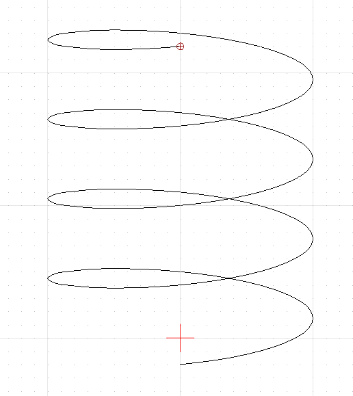
Now, copy and paste as many rotations of the helix you want. These are separate curves, and the end points won't be a perfectly smooth join. If you want them all linked, just select your curves in order, and go to Misc: Information: Store Positions.
Now activate the Spline (SL) tool, and Go to Misc: Information: Use Positions.
A single spline using the same points as your separate ones will be created.
5.png
5.png (8.01 KiB) Viewed 425 times

By varying the proportions of your ellipse and the lead, you can achieve different results using the same method.

Regards,
Derek
QCAD Version 3.29.4 : Windows 10

User avatar
DerekGove
Active Member
Posts: 41
Joined: Sat May 20, 2023 7:10 pm
Location: Cumbria

Re: Corkscrew or streching an ellipse

Post by DerekGove » Sat Mar 16, 2024 10:08 pm

And here's a dxf file with an accurate helix attached, using the same proportions and lead as the last image that Chips&Chips posted...
16x4-L4.png
16x4-L4.png (12.06 KiB) Viewed 420 times
Cheers,
Derek
Attachments
Helix-16x4Ellipse-Lead4.dxf
(134.92 KiB) Downloaded 12 times
QCAD Version 3.29.4 : Windows 10

Post Reply

Return to “QCAD 'How Do I' Questions”