
Morphing
Dieser Inhalt ist noch nicht in deiner Sprache verfügbar.
Introduction
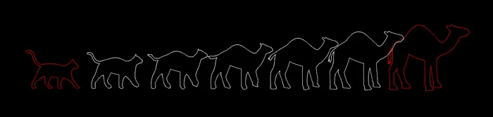
Section titled “Introduction”Morphing in QCAD means to transform a polyline into another polyline in a given number of steps.
Step 1: Preparation
Section titled “Step 1: Preparation”The source and target shape of the morphing operation need to be polylines. You can convert circles, ellipses and splines into polylines using Modify > Explode. Connected segments of lines, arcs, ellipse arcs, splines and open polylines can be joined into single polylines by right-clicking on a segment and choosing Auto Create Polyline.
Open Polylines
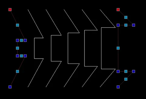
Section titled “Open Polylines”For open polylines, make sure that both polylines have the same direction. You can reverse the direction of a polyline using Modify > Reverse.
For example, if your polylines are vertical strings of lines as shown below, make sure they both have the start point at the top (or bottom). You can see the start point of a polyline highlighted in red if the polylines are selected as shown below. The result of the morphing operation is shown between the selected polylines:
Closed Polylines
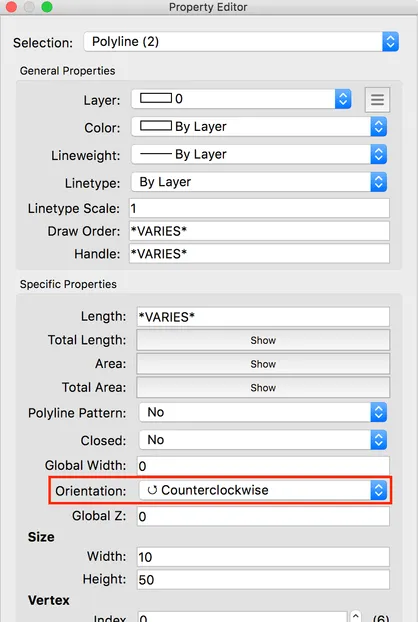
Section titled “Closed Polylines”For closed polylines, make sure that both polylines have the same orientation (clockwise or counterclockwise). Select both polylines and use the property editor to change the property Orientation to either Clockwise or Counterclockwise:
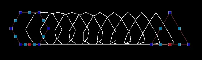
In addition, check that the start points of the closed polylines are aligned to prevent any rotation while morphing. In this example, the start points of the two closed polylines are not aligned and the morphing leads to a rotation type transformation:
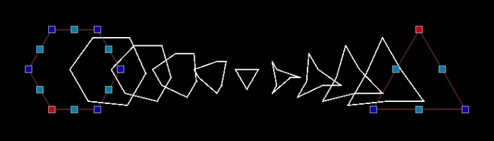
You can relocate the start point of a polyline by right-clicking on it and choosing Relocate Startpoint. Then, click the new position of the start point. This can be on any node or on any segment of the polyline. The morphing is now much smoother:
Polylines with Different Numbers of Segments
Section titled “Polylines with Different Numbers of Segments”If the two polylines have the exact same number of segments, each segment of the source polyline is transformed to the corresponding segment of the target polyline.
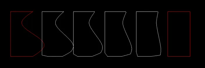
If the two polylines have a different number of segments, a different approach is applied which can lead to a distortion at sharp corners as shown in this example (note the left bottom border being distorted while morphed):
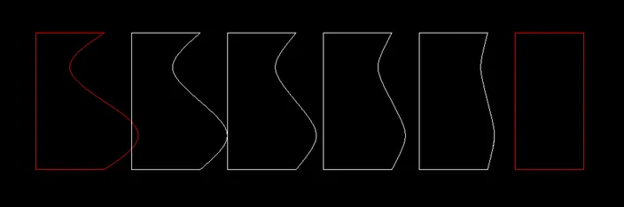
To prevent this effect, split the polyline into two polylines at the top right and bottom right corners using Modify > Divide. Then morph the two polylines individually:
Step 2: Morphing
Section titled “Step 2: Morphing”To morph one polyline to another, choose Polyline > Draw > Morph, click the first polyline and then the second.
The options toolbar at the top allows you to enter the number of steps and choose to interpolate arc segments (for strictly applying morphing also to points on arcs). You can also enter a known custom factor to apply, where 0.0 is on top of the first polyline and 1.0 matches the second polyline. 0.5 would be exactly in the middle. You can also extrapolate by entering a factor > 1.
Examples
Section titled “Examples”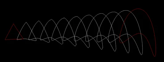
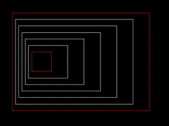
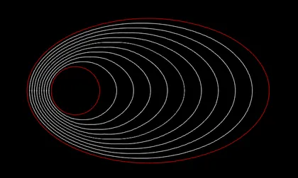
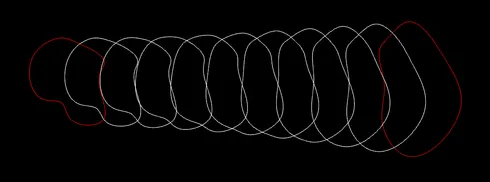
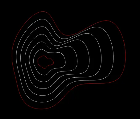
Single polyline:
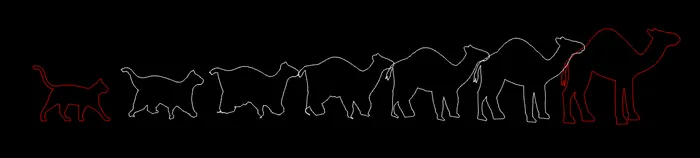
Five separate polylines, split up at strategic places to separate legs, tails, head: