In this QCAD tutorial, we learn about more
advanced printing techniques using layouts and viewports. Example drawing:
birdhouse.dxf We explore how to arrange parts of a drawing
on a paper for printing and how to include a drawing border. For this example, we look at this drawing of a
birdhouse. The drawing is already complete and we are at
a stage where we want to prepare it for printing. However, we do not want to print the drawing
in the same way as shown here in the model space. Instead, we want to rearrange the different
parts of the drawing and present them on two different pages. We also want to add a border and a drawing
title block with information about the drawing. The result should be similar to this example
page. To achieve this in QCAD, we can use layouts
and viewports. In QCAD, a layout represents a sheet of paper
where we prepare the drawing for printing or PDF export. Layouts are a special type of block, so we can
find them in the block list. If the block list is not visible, we need to
show it first using the appropriate button. New drawings created with QCAD contain already
one layout block. In the block list, we can see this special
block. It is called "Layout1". Depending on our version of QCAD, we can also
see the layout blocks of the current drawing as tabs underneath the
drawing area for convenience. We can either click the tab at the bottom or
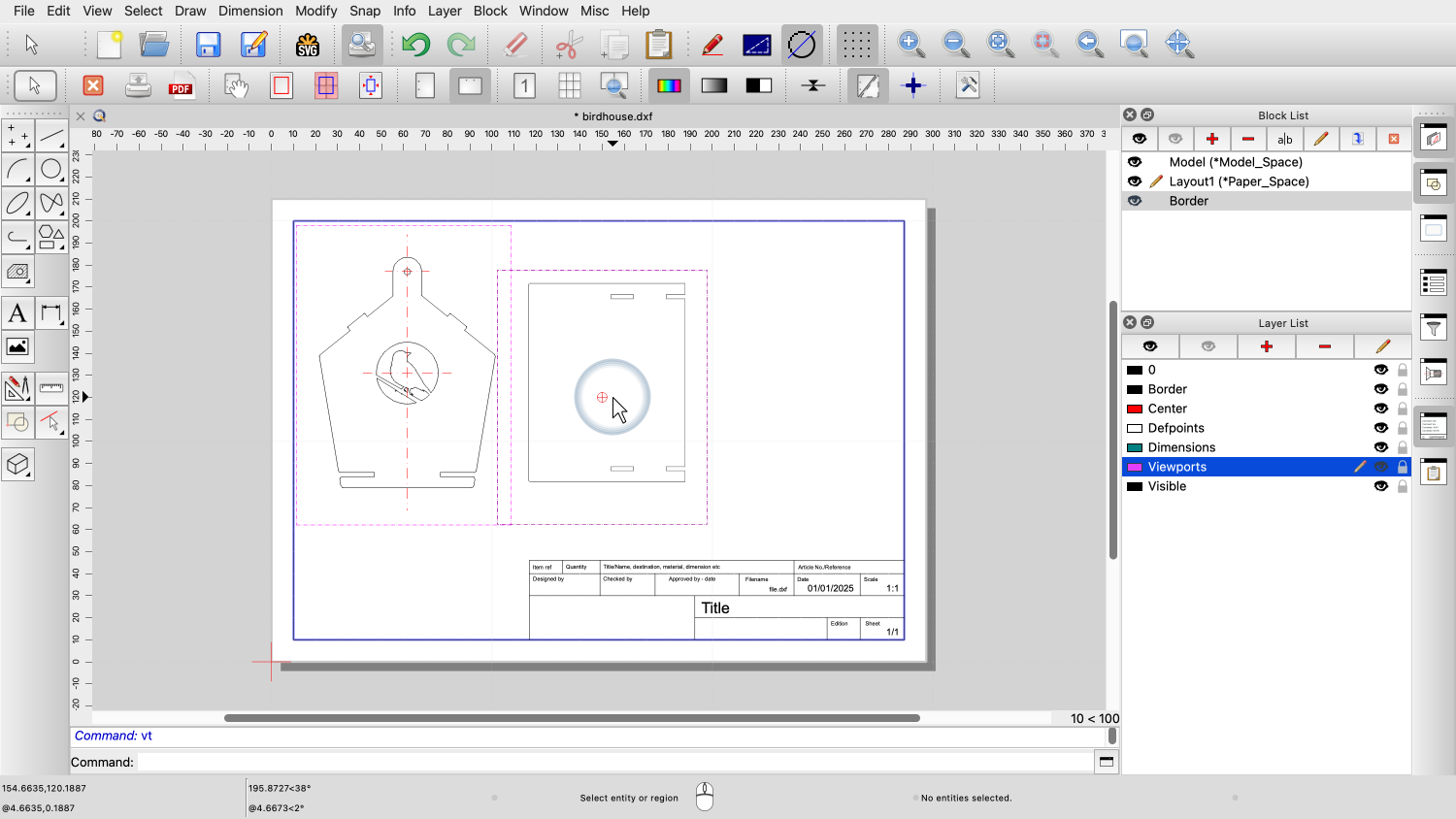
use the block list to open a layout block. Inside the layout block, we can see the page
as it will be printed, similar as in the print preview. The page is still empty because we haven't
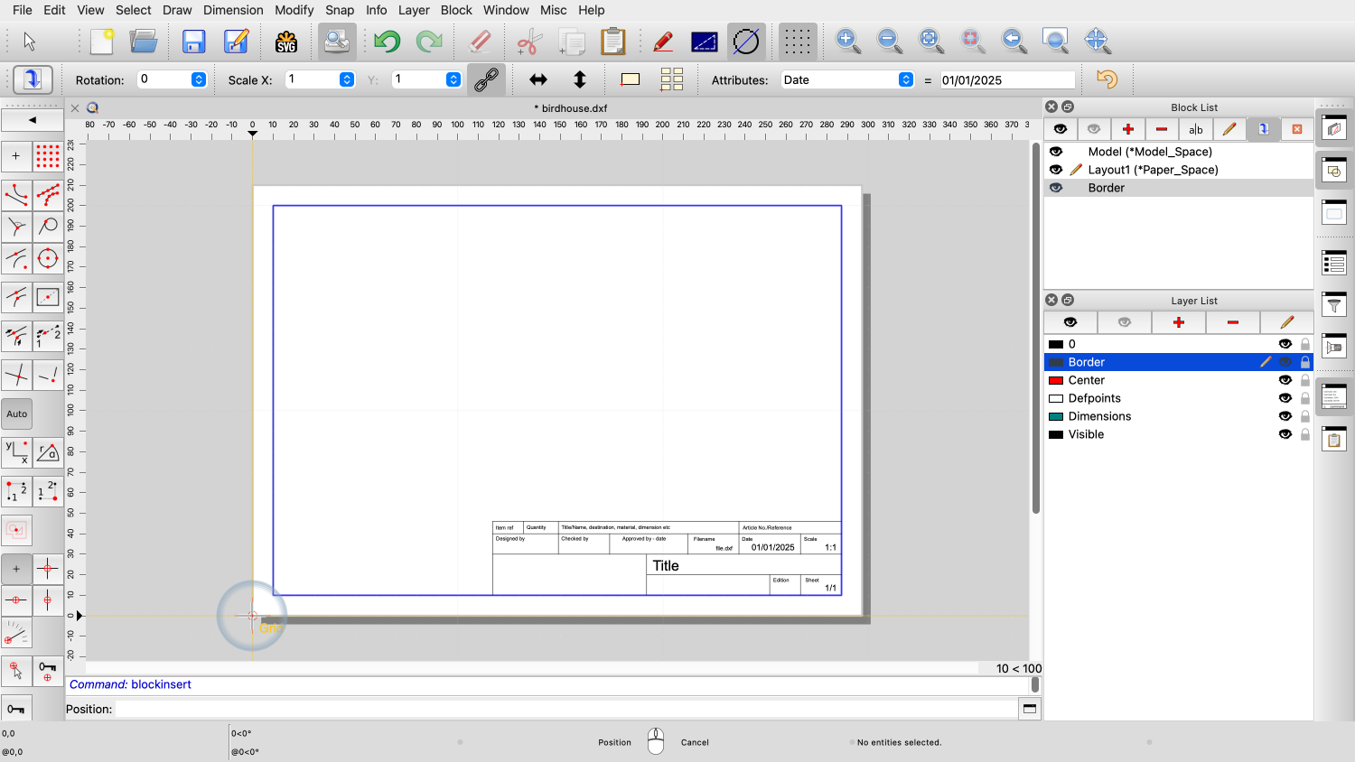
drawn anything into this layout block yet. We start by setting up the page as
desired. For this example, we want to change the paper
orientation to landscape, so we click the landscape button in the
options toolbar at the top. Next, we insert the drawing border which we
have already prepared in a separate block called "Border". Note that the border is drawn in the size of
our paper format, here an A4. All the coordinates and sizes we use when
working on a layout block are paper coordinates and sizes, so we
don't need to scale our border to fit the size of our drawing. We now want to add some parts of our drawing
to the layout. This is done by inserting a so called
viewport. We can think of a viewport as a window that
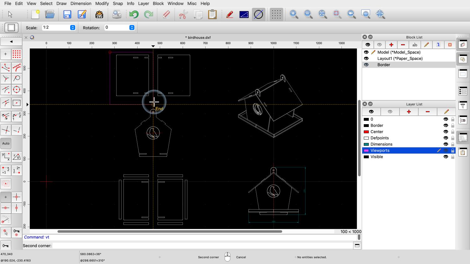
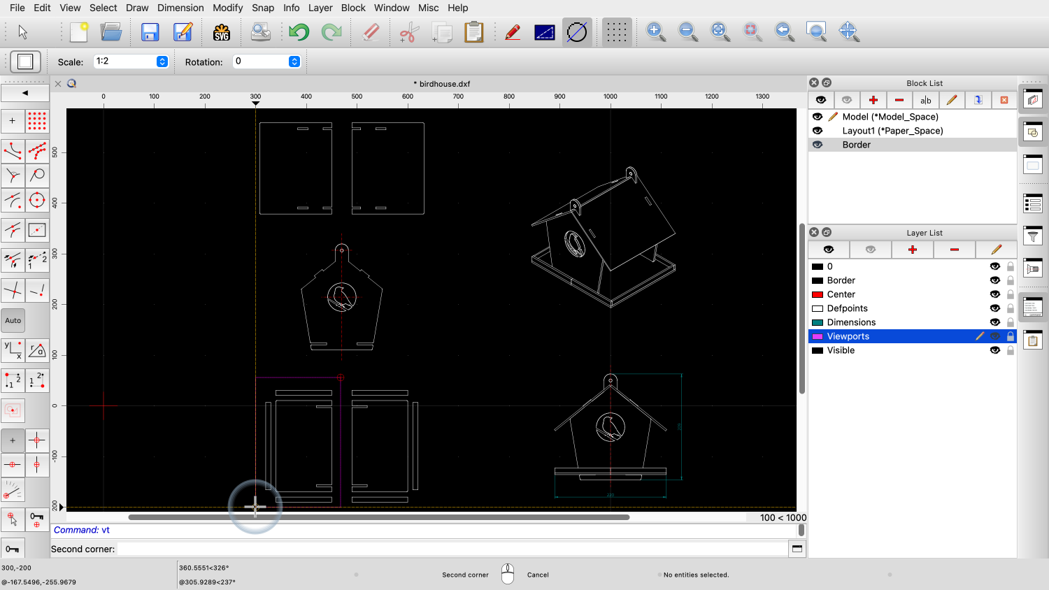
provides a view to a part of the model space. We can find the tool to add a viewport in the
drawing menu. QCAD now shows the model space with our
drawing again. We can now choose what part of the drawing we
want our viewport to show by clicking the two diagonally opposite
corners of a rectangular area. QCAD switches back to the layout where we can
place the viewport. Before we place the viewport, we want to scale
it with a scale of 1:2 to make it fit on our paper. We also want to place all viewports on a
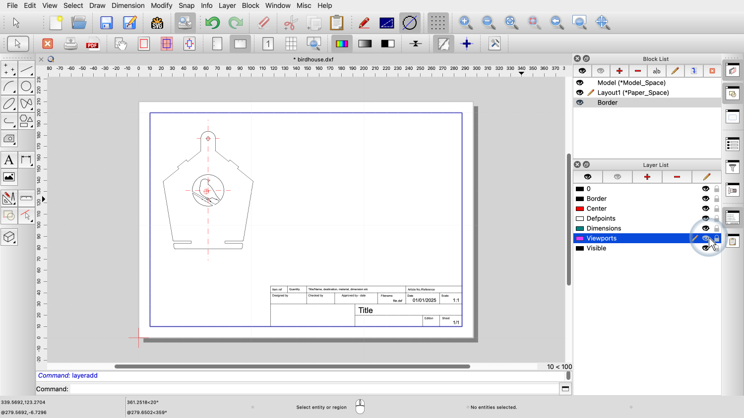
dedicated layer for viewports. We create a layer called Viewports. We give the layer a unique and distinguishable
color, to make sure that our viewports can easily be
identified. We disable this layer for plotting and
printing since we do not want to see the viewport frame on our
printout or PDF. We now place the viewport in our drawing on
our new, dedicated layer for viewports. The frame of the viewport is shown in the
style of our viewport layer. Note that these magenta lines will not be
printed or exported to PDF. We can also hide the viewport layer to give us
a preview without viewport frames. Note that hiding the viewport layer does not
hide the viewport contents but just its frame. This might seem counter-intuitive but is an
important feature to allow us a preview of how the drawing will be
actually printed, without the viewport frames. For now, we switch the viewport layer back on
since we still want to add more viewports. We use the shortcut for the viewport tool to
start the tool again. We choose the part we want to display. And place it in our layout. We repeat this for the last part of our
layout. All that is left is to adjust the drawing
title and other drawing header information. For this example, we want to indicate the
drawing scale we have used for our viewports. And we add the information that this is page
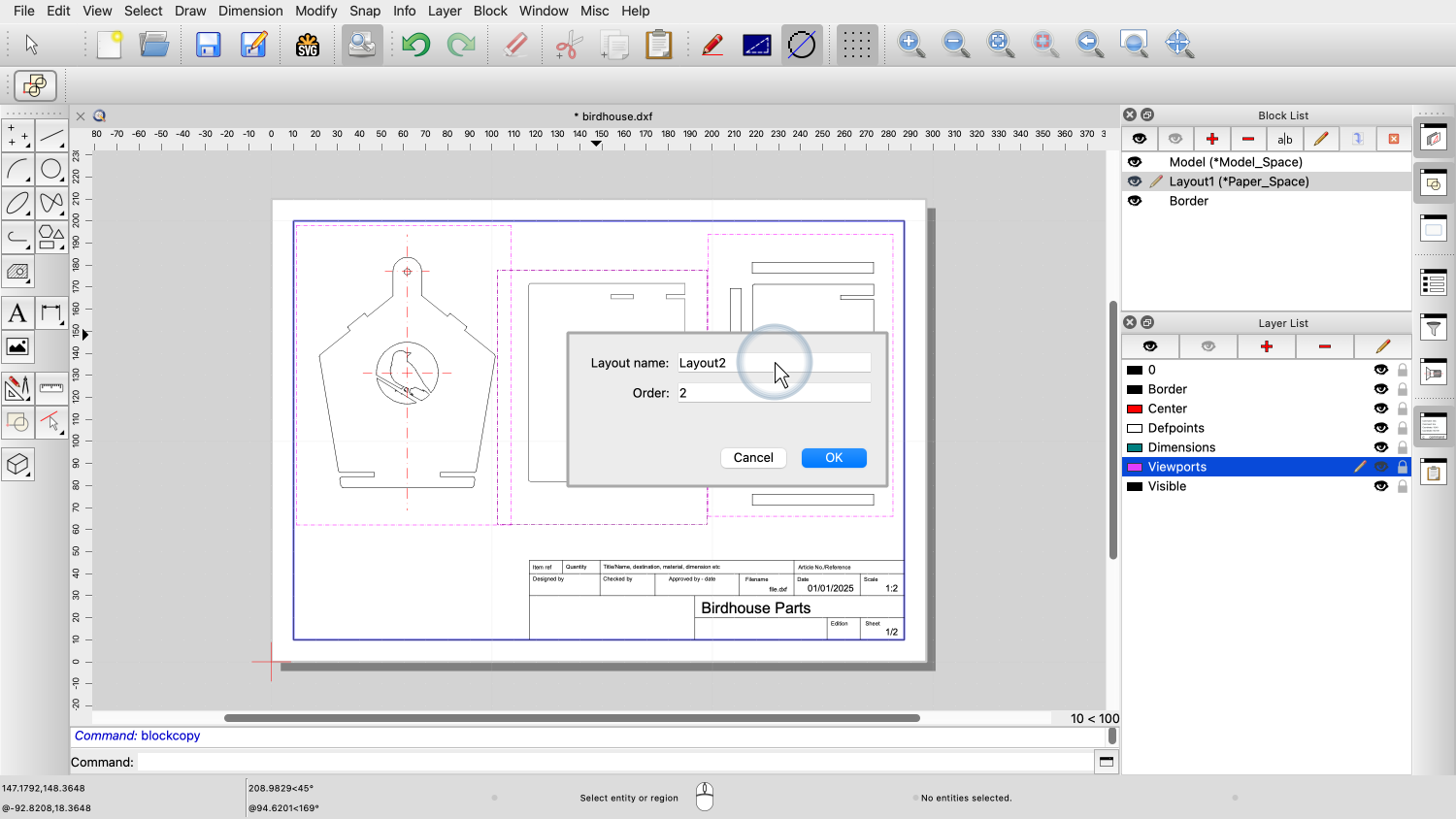
one of two pages. Let's add another layout to our drawing. We can add new, empty layout blocks using the
block menu. However, since our second layout is very
similar to our first one, we choose to duplicate our existing
layout block instead. Our new layout contains now the same border
and viewports as the first layout. We can simply remove the unwanted viewports
and replace them with new ones. We add one viewport for the side view. And we add another viewport for the isometric
view. For the isometric view, we choose a slightly
smaller scale. We might want to adjust the title and other
information about this layout in the drawing header. This is page two of two pages. The last feature we want to show in this
tutorial is the ability to show or hide layers per viewport. For the viewport at the left, we want to hide
the dimension layer. To do this, we double-click the viewport to
bring up the viewport layer dialog. We hide the layers with dimensions and the
center layer for this viewport. The layers of our main drawing and other
viewports are not affected by the choices we make for this
viewport. You should now know how to add and prepare a
layout with viewports for printing. Be sure to practice this with your own
installation. Thank you for watching this QCAD tutorial.Video Transcript